

How To Add Access Point To Cisco Wireless Controller 2504
This certificate serves as a deployment guide for the Cisco 2500 Series Wireless Controller. The Cisco 2500 Series Wireless Controller is a cost-constructive systems-wide wireless solution for retail, enterprise branches, and modest and medium-sized businesses. The controller can calibration in a network equally the network grows.
The Cisco 2500 Series Wireless Controller blends into the Cisco Unified Wireless Network (CUWN) and works with both Cisco lightweight access points (APs) and the Cisco Wireless Control System (WCS) or Cisco Network Control System (NCS) or Prime Infrastructure (PI) in order to provide system-wide wireless LAN functions. The Cisco 2500 Serial Wireless Controller provides real-time advice between wireless APs and other devices in guild to deliver centralized security policies, guest access, wireless intrusion prevention system (wIPS), context-aware (location), Radio Frequency (RF) direction, and quality of services (QoS) for mobility services such every bit voice and video, and OfficeExtend Admission Bespeak (OEAP) support for the teleworker solution.
The Cisco 2500 Series Wireless Controller supports a maximum of l lightweight APs in increments of 5 AP licenses with a minimum of a five AP license, which makes it a cost-constructive solution for retail and small and medium-sized businesses. The Cisco 2500 Serial Wireless Controller offers robust coverage with 802.11 a/b/one thousand or delivers unprecedented reliability with the use of 802.11n, 802.11ac and Cisco Next-Generation Wireless Solutions and Cisco Enterprise Wireless Mesh.
Requirements
There are no specific requirements for this certificate.
Components Used
The information in this document is based on the Cisco 2500 Series Wireless Controller.
Hardware Specifications
-
Data Ports - iv 10 i Gigabit Ethernet Ports
-
Panel Port - 1 ten RJ45
-
External 48V Power Supply
The information in this certificate was created from the devices in a specific lab environment. All of the devices used in this certificate started with a cleared (default) configuration. If your network is live, brand certain that you empathise the potential bear on of any control.
Boosted Features
-
Support for Control and Provisioning of Wireless Access Points (CAPWAP) protocol.
-
Encryption on CAPWAP Data Tunnel (DTLS) (optional).
-
License-based AP count. AP Counts - 50 (in steps of 5, 25, fifty). This was increased to 75 as of Release seven.4 software lawmaking.
-
Supported Client Count - 500 (In all State). This was increased to thou as of Release 7.4 software code.
-
Supported Tag Count - 500.
-
Triple Play Ready - Supports Data, Voice, and Video.
-
500 Mbps of overall traffic throughput (no thing how many ports are connected). This was increased to 1Gbps as of Release 7.iv software code.
-
Link Aggregation Group (LAG) is bachelor only as of Release 7.4 software code and later.
-
In Release 7.iv software lawmaking and afterwards, the 2504 can act as a mobility anchor for upwardly to xv mobility tunnels towards other controllers.
- In Release vii.4, the 2504 started supporting straight continued APs in local mode only. Directly connected APs were not supported earlier that release.
-
The 2504 supports new mobility (that is, mobility with converged access controllers such as the 3850/5760) in Release 8.0 and after.
- Bonjour gateway/multicast Domain Proper noun System (mDNS) is non supported anymore on this controller in version 8.0.132 and further 8.0 maintenace release and viii.1.x and afterwards
Note: The 2504 supports neither the wired guest feature before Version 8.0, nor the multicast-unicast feature (simply multicast-multicast). It likewise does not back up the Lync SDN and Flexconnect AVC features that are introduced in Version 8.1
Note: For an accurate list of supported features, check the release notes for your specific software release, which comprise a Features not supported on WLC 2504 paragraph.
These sections provide a greater insight into the architecture of the Cisco 2500 Series Wireless Controller.
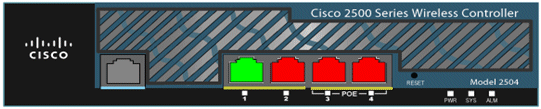
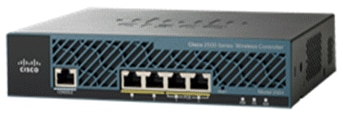
The Cisco 2500 Series Wireless Controller physically has the same form cistron as the Cisco 2106 controller. The CPU on a Cisco 2500 Serial Wireless Controller is a multi-cadre CPU and can handle both data aeroplane and wireless data traffic. The CPU tin can handle control plane application, which handles all the management traffic needed to "command" a wireless network.
The Cisco 2500 Series Wireless Controller has 1 GB system memory. Two types of memory devices are supported in order to store software images. The boot flash contains the boot code, and the meaty flash contains the application lawmaking that can shop multiple images. The forepart panel houses iv Gigabit Ethernet ports. Two of the ports are 802.3af capable. All ports will transfer the traffic to/from the wireless network.
The Cisco 2500 Serial Wireless Controller is powered by an external 48VDC ability brick. The power brick can handle power input from 110VAC to 240VAC.
These tools and information are needed before you lot tin can install the controller:
-
Wireless Controller hardware:
-
Controller with factory-supplied power cord and mounting hardware
-
Network, operating arrangement service network, and AP cables equally required for the CLI console
-
VT-100 concluding emulator on the CLI console (PC, laptop, or palmtop)
-
Null modem serial cable to connect the CLI panel and controller
-
-
Local TFTP server (required in order to download the operating organisation software updates). Cisco uses an integral TFTP server. This means that third-party TFTP servers cannot run on the same workstation as the Cisco WCS because Cisco WCS and third-party TFTP servers use the same communication port.
If the controller is brought up for the starting time fourth dimension with no prior configuration, it automatically enters into a wizard which asks y'all a series of configuration information. The wizard first will first prompt for user ID and password. This wizard cannot be bypassed and you must enter all the information information technology asks.
Caution: Do non connect a PoE cable to the panel port. This activeness amercement the controller.
Before you lot tin can configure the controller for bones operations, yous need to connect it to a PC that uses a VT-100 terminal emulator (such as HyperTerminal, ProComm, Minicom, or Tip). Complete these steps in order to connect the PC to the controller's console port:
-
Plug the RJ-45 connector on a null-modem serial cable into the controller's console port and the other terminate of the cable into the PC's serial port.
-
Start the PC's terminal emulation program.
-
Configure the final emulation program for these parameters:
-
9600 baud
-
eight data bits
-
No catamenia control
-
1 end bit
-
No parity
-
The Cisco 2500 Series Wireless Controller has 4 Gigabit Ethernet ports. Each port is, by default, an 802.1Q VLAN torso port. The VLAN trunking characteristics of the port are not configurable.
An interface is a logical entity on the controller. An interface has multiple parameters associated with it; which iinclude the IP address, default-gateway (for the IP subnet), primary physical port, secondary physical port, VLAN tag, and DHCP server. Since LAG is not used, each interface is mapped to at to the lowest degree one primary physical port and an optional secondary port. Multiple interfaces tin can be mapped to a single Wireless Controller port.
There are multiple types of interfaces on the Wireless Controller, four of which are static types that must be present and are configured at setup fourth dimension:
-
Management interface (static and configured at setup time; mandatory)
-
AP-manager interface - Not required for the Cisco 2500 Series Wireless Controller
-
Virtual interface (static and configured at setup fourth dimension; mandatory)
-
Dynamic interface (user-defined)
The management interface is the default interface for in-band management of the controller and connectivity to enterprise services such as Authentication, Say-so, and Accounting (AAA) servers. The management interface is too used for communications between the controller and APs. The management interface is the only consistently "pingable" in-band interface IP address on the controller. The direction interface acts like an AP manager interface by default.
The dynamic interface with the "Dynamic AP Direction" option enabled on information technology is used equally the tunnel source for packets from the controller to the AP, and as the destination for CAPWAP packets from the AP to the controller. The dynamic interfaces for AP manager must have a unique IP accost. Typically, this is configured on the same subnet as the management interface, but this is non necessarily a requirement. In the example of the Cisco 2500 Series Wireless Controller, a single dynamic AP manager can support any number of APs. Withal, as a best practice, it is suggested to have 4 separate dynamic AP manager interfaces and associate them to the 4 Gigabit interfaces. Past default, the management interface acts like an AP-manager interface also and it is associated to one Gigabit interface. As a result, if yous use the management interface, you need to create only 3 more dynamic AP manager interfaces and associate them to the remaining 3 Gigabit interfaces.
Note: If you use AP manager interfaces, the CAPWAP DISCOVERY packet that is sent initially by the APs in order to discover the WLC is however sent towards the management interface IP address. The management interface replies with a CAPWAP DISCOVERY RESPONSE in guild to requite the list of AP manager interfaces of the WLC. This means that the APs always need UDP 5246 and 5247 reachability to the controller management interface and that the DHCP option 43 must mention only the management interface IP address, not the AP director IP addresses.
The virtual interface is used to back up mobility management, DHCP relay, and embedded Layer 3 security similar guest web hallmark and VPN termination. The virtual interface must be configured with an unassigned and unused gateway IP address. A typical virtual interface is 1.ane.1.i. The virtual interface accost is not pingable and should not exist in any routing table in your network.
Dynamic interfaces are created past users and are designed to be coordinating to VLANs for wireless LAN client device. The Cisco 2500 Series Wireless Controller will support up to 16 dynamic interfaces. Dynamic interfaces must be configured on a unique IP network and VLAN. Each dynamic interface acts as a DHCP relay for wireless clients associated to wireless LANs (WLANs) mapped to the interface. A WLAN assembly a Service Set Identifier (SSID) to an interface and is configured with security, QoS, radio policies, and other wireless network parameters. In that location can be up to xvi WLANs configured per controller. Direction servers, such as a radius server and NTP server, should non be in a dynamic interface subnet just should be either in the management interface subnet or any other subnet not added to the WLC.
Annotation: LAG is supported on the Cisco 2500 Serial Wireless Controller only on Release vii.iv software lawmaking and afterward.
By default, all iv ports on the Cisco 2500 Series Wireless Controller are 802.1Q body ports. The controller is always connected to a Gigabit Ethernet port on the neighboring switch. The neighbour switch port is configured every bit an 802.1Q torso and only the advisable VLANs are immune on the trunk. All other VLANs are pruned. This is not necessary, but is a deployment best practice because when irrelevant VLANs are pruned, the controller just processes relevant frames which optimizes performance.
This is the 802.1Q switchport configuration:
switchport
switchport body encapsulation dot1q
switchport trunk native vlan 10
switchport torso allowed vlan Ten
switchport way trunk
end
Configure the Controller With the Startup Sorcerer
This wizard output is taken from Release seven.four software, so it might be slightly dissimilar in other software releases.
(Cisco Controller) (Cisco Controller)Welcome to the Cisco Magician Configuration Tool
Use the '-' graphic symbol to backupWould you like to cease autoinstall? [yeah]:
Auto-INSTALL: starting now...
rc = 0
Car-INSTALL:no interfaces registered.
AUTO-INSTALL: process terminated - no configuration loadedArrangement Name [Cisco_b2:19:c4] (31 characters max):
WLC
Enter Administrative User Proper noun (24 characters max): admin
Enter Administrative Password (3 to 24 characters): *******
Re-enter Administrative Password : *******Enable Link Aggregation (LAG) [yes][NO]:
noManagement Interface IP Address:
10.48.39.212
Management Interface Netmask: 255.255.255.0
Management Interface Default Router: 10.48.39.5
Direction Interface VLAN Identifier (0 = untagged): 0
Direction Interface Port Num [i to four]: 1
Management Interface DHCP Server IP Accost: x.48.39.5Virtual Gateway IP Address:
1.1.1.1Multicast IP Address:
239.ane.1.oneMobility/RF Group Proper noun:
NicoNetwork Name (SSID):
noneConfigure DHCP Bridging Mode [yes][NO]:
noAllow Static IP Addresses [Aye][no]:
ayeConfigure a RADIUS Server at present? [Yep][no]:
no
Warning! The default WLAN security policy requires a RADIUS server.
Delight see documentation for more details.Enter Country Code list (enter 'help' for a list of countries) [US]:
BeEnable 802.11b Network [YES][no]:
aye
Enable 802.11a Network [Yep][no]: yes
Enable 802.11g Network [YES][no]: yes
Enable Car-RF [Yeah][no]: yesConfigure a NTP server now? [Aye][no]:
yes
Enter the NTP server's IP address: 10.48.39.33
Enter a polling interval betwixt 3600 and 604800 secs: 3600Configuration correct? If yep, arrangement will save it and reset. [yeah][NO]:
yesConfiguration saved!
Resetting arrangement with new configuration...Configuration saved!
Resetting system
Annotation: The previous configuration is an instance. It might differ from one install to another.
(Cisco Controller) >show sysinfoManufacturer'southward Name.............................. Cisco Systems Inc.
Production Name..................................... Cisco Controller
Product Version.................................. 7.4.121.0
Bootloader Version............................... 1.0.twenty
Field Recovery Paradigm Version..................... 7.6.101.1
Firmware Version................................. PIC sixteen.0Build Type....................................... Data + WPS
System Name...................................... WLC
System Location..................................
System Contact...................................
System ObjectID.................................. 1.3.6.1.iv.1.9.1.1279
IP Address....................................... 10.48.39.212
Concluding Reset....................................... Software reset
Organization Upward Time................................... 0 days 0 hrs 14 mins 58 secs
Organization Timezone Location.........................
System Stats Realtime Interval................... 5
Organization Stats Normal Interval..................... 180--More than-- or (q)uit
Configured Country............................... Be - Belgium
Operating Environment............................ Commercial (0 to 40 C)
Internal Temp Alarm Limits....................... 0 to 65 C
Internal Temperature............................. +31 C
External Temperature............................. +35 C
Fan Status....................................... 4300 rpmState of 802.11b Network......................... Enabled
State of 802.11a Network......................... Enabled
Number of WLANs.................................. 1
Number of Active Clients......................... 0Retention Current Usage............................. Unknown
Memory Average Usage............................. Unknown
CPU Current Usage................................ Unknown
CPU Average Usage................................ UnknownBurned-in MAC Address............................ 84:78:Ac:B2:19:C0
Maximum number of APs supported.................. 75
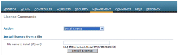
License Installation
The Cisco 2500 Series Wireless Controller does not have any licenses installed. Without any installed licenses, the APs volition not be able to join the controller. Information technology is recommended to install appropriate licenses on the Cisco 2500 Serial Wireless Controller in lodge to work with the controller as you get forward. The Cisco 2500 Series Wireless Controller is shipped with an evaluation license for a period of lx days (that is, viii weeks 4 days). The evaluation license is a base license only.
The ordered license can exist installed on the controller with either the CLI or the GUI. The license installed tin be checked through both the CLI and the GUI. In both cases, at that place should be a TFTP server that hosts the license files.
(Cisco Controller) >license install ?
<url>          tftp://<server ip>/<path>/<filename>
(Cisco Controller)
The show license all command displays the installed licenses.
Note: This license includes a information DTLS functionality.
(Cisco Controller) >evidence license allLicense Store: Primary License Storage
StoreIndex: 2 Feature: base of operations-ap-count Version: one.0
License Blazon: Permanent
License State: Active, In Use
License Count: 50/50/0
License Priority: Medium
StoreIndex: three Feature: data encryption Version: 1.0
License Type: Permanent
License Country: Active, In Use
License Count: Non-Counted
License Priority: Medium
License Store: Evaluation License Storage
StoreIndex: 0 Feature: base Version: 1.0
License Type: Evaluation
License Land: Agile, Not in Use, EULA accepted
Evaluation total period: 8 weeks four days
Evaluation menstruum left: 8 weeks four days
License Count: Non-Counted
License Priority: Low
StoreIndex: 1 Characteristic: base-ap-count Version: 1.0
License Type: Evaluation
License Land: Inactive
Evaluation total period: viii weeks iv days
Evaluation period left: 8 weeks 4 days
License Count: fifty/0/0
License Priority: None
(Cisco Controller) >
Enable DTLS in the Cisco 2500 Series Controller
In lodge to enable DTLS on an AP or particularly on a group of APs, make sure that y'all take Data Encryption License installed in the controller. DTLS (Data Encryption) can be enabled on a per AP basis from the Avant-garde tab once you select the AP details.
Select an AP, go to the Advanced tab, and check the Data Encryption cheque box.

(Cisco Controller) >config ap link-encryption enable ?
<Cisco AP> Enter the name of the Cisco AP. all Apply the configuration for
all capable Cisco AP
(Cisco Controller) >config ap link-encryption enable J-3502E
(Cisco Controller) >prove ap link-encryption all
Encryption Dnstream Upstream Final
AP Name Land Count Count Update
-------------- --- -------- -------- ------
J-3502E En 102 747 22:12
J-1262 Dis 0 0 22:12
J-1040 Dis 0 0 22:13
J-1140 Dis 0 0 22:10(Cisco Controller) >
show dtls connectionsAP Name Local Port Peer IP Peer Port Ciphersuite
------------ ------------- ------------- ---------- ------------------
J-3502E Capwap_Ctrl ten.10.10.116 41066 TLS_RSA_WITH_AES_128_CBC_SHA
J-3502E Capwap_Data x.10.10.116 41066 TLS_RSA_WITH_AES_128_CBC_SHA
J-1262 Capwap_Ctrl ten.ten.10.120 45543 TLS_RSA_WITH_AES_128_CBC_SHA
J-1040 Capwap_Ctrl x.ten.ten.122 65274 TLS_RSA_WITH_AES_128_CBC_SHA
J-1140 Capwap_Ctrl ten.10.10.123 4825 TLS_RSA_WITH_AES_128_CBC_SHA(Cisco Controller) >
PI is the electric current direction software used to manage the Cisco 2500 Series Wireless Controller. Earlier versions were called WCS or NCS. It provides advanced management tools like wireless coverage display and location-based services. In that location is a close relation between the software version of the management organization (Prime Infrastructure/NCS/WCS) and the WLC software version. See the wireless software compatibility matrix equally well as the Prime number Infrastructure and WLC release notes for supported compatible releases. Prime Infrastructure uses SNMP in club to manage wireless controllers, access points, and client devices. The Cisco 2500 Series Wireless Controller devices need to have SNMP configured correctly.
Complete these steps:
-
Log in to the PI web interface with the URL:
https://<prime-ip-accost>
-
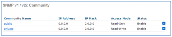
SNMPv2 is configured on the Cisco 2500 Series Wireless Controller. In order to configure SNMPv2 through the Controller web interface, select Management > SNMP > Communities. The Cisco 2500 Series Wireless Controller defaults are Read-Only customs public and Read-Write community private. Add new communities or alter as necessary. For simplicity, the defaults are used.
-
In the PI interface, select Operate > Device work center. Select Add device from the card bar. Notation that this might differ dependent upon if you utilize the classic theme from PI or if you ucs NCS or WCS.
-
Enter the IP Address of the Cisco 2500 Series Wireless Controller management interface and configure the appropriate SNMP parameters. Click OK.
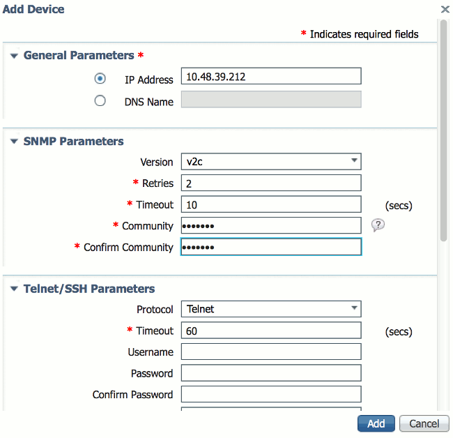
The controller is added successfully and the Cisco 2500 Series Wireless Controller is ready to be provisioned by PI.
In lodge to verify the Cisco 2500 Serial Wireless Controller later on it is added in PI, go check dorsum in the device work center if it is successfully synced and managed. Wrong SNMP credentials might leave it "unmanaged".
The Cisco 2500 Series Wireless Controller provides a cost effective Unified wireless solution. Although the controller has multiple ten/100/1000 ports, information technology does non conduct like switches or routers. Information technology is not recommended to utilize different ports equally a hub/switch implementation. This fundamental point is a key aspect to get the all-time functioning out of the controller.
The Cisco 2500 Serial Wireless Controller supports multiple uplink ports. In Release 7.four and later y'all can use LAG in order to build an etherchannel and treat several ports as just i connectedness. Or, you can disable LAG and configure a arrangement where direction and dynamic interfaces tin be configured on different concrete ports, and data traffic can switch back and forth infra network from respective physical ports.
The Cisco 2500 Series Wireless Controller as well supports multiple AP-managers (for AP Load Balancing) where multiple AP-managers tin exist configured in addition to an AP-manager which is bounded with a management interface. In this case, it is recommended to accept all AP-managers in the same subnet every bit a management interface.
<CISCO2504> >show interface summaryInterface Proper name Port Vlan Id IP Accost Type Ap Mgr Invitee
--------------------- ---- -------- -------------- ------- ------ -----
apmgr2 2 10 10.ten.ten.12 Dynamic Yes No
apmgr3 3 10 10.10.10.13 Dynamic Yes No
apmgr4 4 10 10.10.10.14 Dynamic Yeah No
management one 10 10.x.x.10 Static Yes No
virtual N/A N/A 1.1.ane.1 Static No No<CISCO2504> >
Annotation: Configuration of interfaces on unlike ports that are in the same VLAN is non supported and will break connectivity equally per Cisco bug ID CSCux75436. Information technology but works in this example when an AP manager is present on each of those ports. If the interface created is not an AP manager and is in the same VLAN as another port, routing issues volition occur.
In the in a higher place output, the management interface and AP-director are bounded together to port 1. 3 more AP-managers are created on other concrete ports (2, 3, and iv) in the same subnet as management interfaces.
APs that join the controller are load counterbalanced such that each port on the controller shares the load of the 50 APs. Each port in the previous configuration allows 13 APs to join the controller.
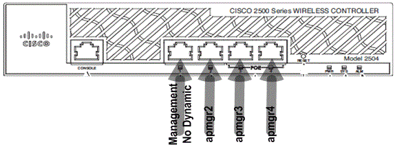
Information technology is also possible to take multiple AP-managers in a unlike subnet than the management interface. However, in this case, it is recommended that y'all disable the AP-manager from the direction interface and create another AP-managing director interface on unlike concrete ports in a dissimilar subnet than the management interface. All multiple AP-managers in this scenario should be in the aforementioned subnet.
<CISCO2504> >prove interface summaryInterface Name Port Vlan Id IP Address Type Ap Mgr Guest
--------------------- ---- -------- -------------- ------- ------ -----
apmgr2 two 11 10.10.11.12 Dynamic Yep No
apmgr3 iii eleven ten.ten.xi.13 Dynamic Yes No
apmgr4 4 11 ten.10.eleven.fourteen Dynamic Yep No
management 1 10 10.ten.ten.10 Static No No
virtual North/A Northward/A 1.ane.ane.1 Static No No<CISCO2504> >

In the previous output, direction and AP-managing director are not bounded. In this scenario, multiple AP-managers can be created in a different subnet from the management interface and mapped to different physical ports.
Annotation: The internal DHCP server only works (for wireless clients) with DHCP proxy enabled.
Some of the scenarios supported by the Cisco 2500 Series Wireless Controller are described here with sample configurations.
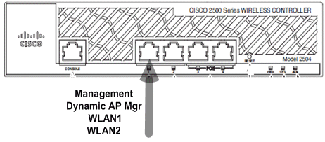
Scenario 1
The management interface with an embedded AP-Manager is configured on Port 1. Two WLANs are configured on the controller. WLAN ane and WLAN 2 are mapped to the management interface.
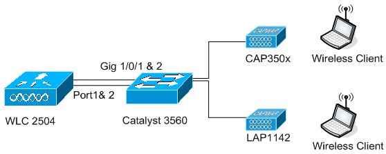
A unproblematic topology has the Cisco 2500 Serial Wireless Controller connected to a Goad 3560 switch. Gigabit Ethernet port 1 on the controller is connected to Gigabit Ethernet port ane/0/1 on the switch.

Switch#sh run int gig one/0/1
Building configuration...Current configuration : 123 bytes
!
interface GigabitEthernet1/0/i
switchport trunk encapsulation dot1q
switchport manner torso
spanning-tree portfast
finishSwitch#
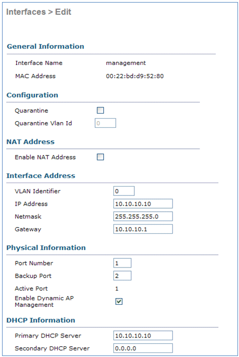
The direction interface configuration on the Cisco 2500 Series Wireless Controller is straightforward and has dynamic AP management enabled.

Ii WLANs are configured. WLAN1 and WLAN2 are mapped to the management interface and service clients.
<CISCO2504> >show wlan summNumber of WLANs.................................. 2
WLAN ID WLAN Profile Name / SSID Status Interface Name
------- ------------------------------------- -------- --------------------
1 WLAN1 / WLAN1 Enabled management
ii WLAN2 / WLAN2 Enabled management<CISCO2504> >
Internal DHCP Server with DHCP Proxy Enabled
The DHCP server TestVlan10 is configured on the controller and this scope services APs and clients. The DHCP server configuration on the controller is unproblematic.
<CISCO2504> >testify dhcp summaryScope Proper name Enabled Address Range
TestVlan10 Yep 10.10.10.100 -> 10.x.10.200<CISCO2504> >show dhcp detailed TestVlan10
Scope: TestVlan10Enabled................................... Yes
Lease Fourth dimension................................ 36400 <10 hours half dozen minutes forty seconds>
Pool Outset................................ 10.10.10.100
Pool End.................................. x.x.ten.200
Network................................... x.10.10.0
Netmask................................... 255.255.255.0
Default Routers........................... 10.x.x.10 0.0.0.0 0.0.0.0
DNS Domain................................
DNS....................................... 0.0.0.0 0.0.0.0 0.0.0.0
Netbios Name Servers...................... 0.0.0.0 0.0.0.0 0.0.0.0<CISCO2504> >
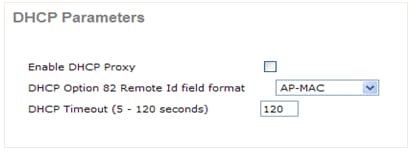
This is the DHCP configuration capture from the GUI of the Cisco 2500 Series Wireless Controller:
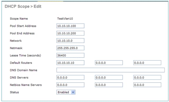
The DHCP Proxy is enabled on all Cisco controllers by default.

In the all of the previous configurations, VLAN10 is non tagged on the switch. All traffic from the switch is sourced to Port 1 on the controller. APs and client traffic are forwarded to the controller untagged.
APs are continued to the Catalyst switch with these switchport configurations. The switchport tin can either be trunked or configured to be an access port.
Switch#sh run int gig 1/0/nine
Building configuration...Current configuration : 132 bytes
!
interface GigabitEthernet1/0/9
switchport trunk encapsulation dot1q
switchport trunk native vlan 10
switchport mode trunk
endSwitch#sh run int gig one/0/10
Building configuration...Electric current configuration : 66 bytes
!
interface GigabitEthernet1/0/10
switchport admission vlan 10
endSwitch#
The AP can join the controller and the status of the AP can exist verified on the controller. At that place are ii APs that accept joined the controller and can be confirmed by the condition in this capture:
<CISCO2504> >show ap join stats summary allNumber of APs.............................................. 2
Base Mac AP EthernetMac AP Name IP Address Status
00:22:ninety:96:69:00 00:22:ninety:90:ab:d3 AP0022.9090.abd3 10.10.10.103 Joined
ec:44:76:b9:7d:c0 c4:7d:4f:3a:e3:78 APc47d.4f3a.e378 10.x.ten.105 Joined<CISCO2504> >show ap summary
Number of APs.................................... 2
Global AP User Name.............................. Not Configured
Global AP Dot1x User Name........................ Non ConfiguredAP Proper name Slots AP Model Ethernet MAC Location
---------------- ----- ----------------- ----------------- ----------------
AP0022.9090.abd3 two AIR-LAP1142N-A-K9 00:22:90:xc:ab:d3 default location
APc47d.4f3a.e378 ii AIR-CAP3502E-A-K9 c4:7d:4f:3a:e3:78 default locationPort Land Priority
---- ------- ------
1 U.s.a. 1
one United states 1
The APs that have joined the controller can also be verified past the AP's summary on the controller. Configure both the AP name and the location of the AP install.
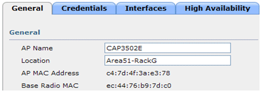
Configure the controller name and IP address under High Availability in order to prime the AP.
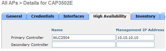
With this configuration, the AP joins the configured controller every bit the first preference.
External DHCP Server with DHCP Proxy Disabled
This is a general setup that has been in do for all Cisco controllers for some deployments. The configurations are almost the same equally noted previously, but have the DHCP Proxy disabled.
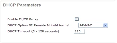
The AP-managing director interfaces in this scenario signal to an external DHCP server.
Notation: Information technology is recommended to enable either an internal DHCP server or an external DHCP server.
ip dhcp excluded-address 10.x.11.ane x.10.11.150
!
ip dhcp pool VLAN11
          network 10.10.xi.0 255.255.255.0
          default-router 10.10.11.1
!
External DHCP Server with DHCP Proxy Enabled
This is a general setup that is i of the all-time practices for all Cisco controllers. The configurations are almost the same as noted in the previous with DHCP Proxy enabled.
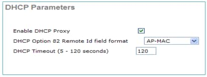
The management interface in this scenario is always directed to an external DHCP server.
ip dhcp excluded-address ten.ten.xi.ane 10.x.11.150
!
ip dhcp pool VLAN11
          network 10.10.11.0 255.255.255.0
          default-router 10.x.11.1
!
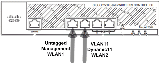
Scenario 2
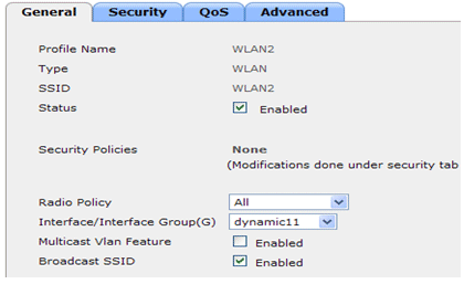
The management interface with AP-director enabled is mapped to port 1. Dynamic interface dynamic11 is mapped to another physical interface (port 2) for data traffic. WLAN 1 is mapped to the management interface and WLAN 2 is mapped to the dynamic interface.
One more DHCP telescopic is configured on the controller. This configured DHCP Scope TestVlan11 is mapped to the dynamic-interface configured on the controller.
<CISCO2504> >prove dhcp summaryScope Name Enabled Accost Range
TestVlan10 Yep x.10.10.100 -> 10.10.10.200
TestVlan11 Yeah 10.10.xi.100 -> 10.10.eleven.200<CISCO2504> >show dhcp detailed TestVlan11
Scope: TestVlan10Enabled................................... Yep
Lease Fourth dimension................................ 36400 <10 hours 6 minutes 40 seconds>
Puddle Start................................ x.10.11.100
Puddle End.................................. ten.x.eleven.200
Network................................... 10.ten.11.0
Netmask................................... 255.255.255.0
Default Routers........................... 10.10.11.10 0.0.0.0 0.0.0.0
DNS Domain................................
DNS....................................... 0.0.0.0 0.0.0.0 0.0.0.0
Netbios Proper noun Servers...................... 0.0.0.0 0.0.0.0 0.0.0.0<CISCO2504> >
Internal DHCP Server with DHCP Proxy Enabled
By default, the DHCP Proxy is enabled on the controller equally seen in one of the previous captures. Dynamic interface dynamic11 is configured and is mapped to VLAN11. The interface is besides mapped to the configured internal DHCP server. The dynamic interface is not enabled for dynamic AP management.
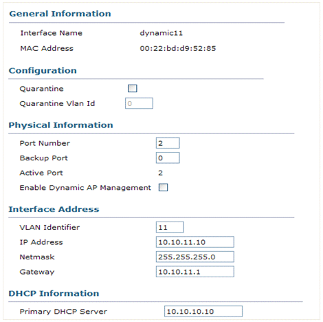
1 of the configured WLANs is mapped to the management interface and the second WLAN is mapped to the configured dynamic interface dynamic11. The primary DHCP server is a necessity for configuration in this scenario, but should exist pointed to the direction interface.
External DHCP Server with DHCP Proxy Disabled
Clients successfully become IP addresses from the configured external DHCP server. Verify the status of the internal DHCP server and make sure that the internal DHCP server is disabled.

External DHCP Server with DHCP Proxy Enabled

Clients successfully become IP addresses from the configured external DHCP server.
Scenario 3
The management interface with AP-manager enabled is mapped to port 1. Port 2 is configured to be a backport. WLAN one is mapped to the management interface.
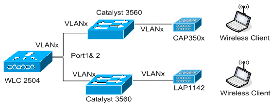
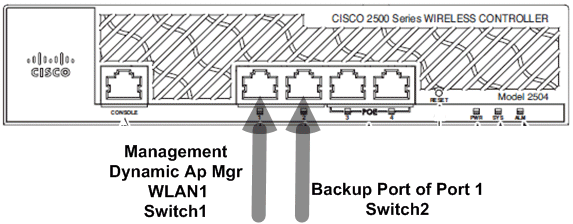
In this scenario the management and dynamic interfaces are configured on Port ane with either the internal DHCP server or the external DHCP server. Ports 1 and 2 are connected to 2 different switches. This provides redundancy to the Layer 2 and Layer three switch network as shown in this topology and interface captures.
Scenario 4 : LAG
In Release 7.4 and after software on the WLC, information technology is possible to configure LAG. Note that the overall 2504 WLC throughput stays 1 Gbps no matter how many ports you connect.
In this scenario, port 1 and two of the WLC 2504 were continued to the same switch on port viii and 10 bundled into port-channel 1. Information technology is required to plug all WLC ports to the same switch (unless in the example of two catalyst 6000 in VSS or Nexus in VPC).
(Cisco Controller) >show port summarySTP Admin Physical Physical Link Link
Pr Type Stat Mode Mode Condition Condition Trap POE
-- ------- ---- ------- ---------- ---------- ------ ------- -------
one Normal Forw Enable Automobile 1000 Total Up Enable N/A
2 Normal Forw Enable Machine g Full Up Enable Northward/A
3 Normal Disa Enable Car Auto Down Enable North/A
4 Normal Disa Enable Auto Auto Down Enable N/A(Cisco Controller) >show lag summary
LAG Enabled
(Cisco Controller) >show interface summary
Number of Interfaces.......................... 2
Interface Name Port Vlan Id IP Address Type Ap Mgr Guest
-------------------------------- ---- -------- --------------- ------- ------ -----
management LAG untagged 10.48.39.212 Static Yes No
virtual N/A N/A i.1.1.one Static No No(Cisco Controller) >testify interface detailed direction
Interface Name................................... management
MAC Address...................................... 84:78:ac:b2:19:cf
IP Accost....................................... 10.48.39.212
IP Netmask....................................... 255.255.255.0
IP Gateway....................................... 10.48.39.v
External NAT IP Country............................ Disabled
External NAT IP Accost.......................... 0.0.0.0
VLAN............................................. untagged
Quarantine-vlan.................................. 0
Active Physical Port............................. LAG (13)
Primary Physical Port............................ LAG (13)
Fill-in Physical Port............................. Unconfigured
DHCP Proxy Mode.................................. Global
Primary DHCP Server.............................. 10.48.39.v
Secondary DHCP Server............................ Unconfigured
DHCP Option 82................................... Disabled
ACL.............................................. Unconfigured
mDNS Profile Proper noun................................ Unconfigured
AP Managing director....................................... Yes
Invitee Interface.................................. No
L2 Multicast..................................... Enabled
You tin can meet that it is now impossible to select ports for interfaces on the WLC as they are all fastened to the LAG port package (which will e'er show as number 13).
On the switch, all ports that participate in the parcel must accept the exact same configuration (specially trunk native VLAN and allowed VLANs). In this case, allowed VLANs were express to what will be used on the WLC which is a best practice.
One time the interfaces are bundled together with the command channel-group X mode on, a port channel interface of number X is created. Any farther change of the configuration should be completed on the port aqueduct interface and not on the individual ports anymore.
Nico3560C#evidence run int g0/viii
Edifice configuration...Current configuration : 208 bytes
!
interface GigabitEthernet0/8
switchport admission vlan 33
switchport trunk encapsulation dot1q
switchport trunk allowed vlan 1,30-39
switchport manner body
mls qos trust dscp
channel-grouping 1 mode on
terminateNico3560C#testify run int g0/x
Edifice configuration...Current configuration : 182 bytes
!
interface GigabitEthernet0/10
switchport trunk encapsulation dot1q
switchport body allowed vlan 1,xxx-39
switchport mode trunk
mls qos trust dscp
aqueduct-grouping 1 mode on
endNico3560C#show etherchannel 1 summ
Flags: D - downwardly P - bundled in port-channel
I - stand up-solitary south - suspended
H - Hot-standby (LACP merely)
R - Layer3 South - Layer2
U - in utilize f - failed to allocate aggregatorGrand - not in use, minimum links not met
u - unsuitable for bundling
w - waiting to exist aggregated
d - default portNumber of channel-groups in apply: ane
Number of aggregators: 1Group Port-aqueduct Protocol Ports
------+-------------+-----------+-----------------------------------------------
ane Po1(SU) - Gi0/8(P) Gi0/10(P)Nico3560C#
Nico3560C#show run int po1
Edifice configuration...Current configuration : 131 bytes
!
interface Port-channel1
switchport torso encapsulation dot1q
switchport trunk immune vlan 1,30-39
switchport mode torso
end
The command eterchannel load-balance src-dst-ip is too required on the switch globally for this to work.
These are only a few designs implemented by users in order to leverage the wireless service to their client devices with CUWN.
Ethernet ports on the Cisco 2500 Series Wireless Controllers do non work as Switch ports (that is, two machines straight connected to these ports cannot communicate with each other). You should non connect servers, such as DHCP, TFTP, and and so on, on these ports and look Wireless Clients and APs to receive an IP address from this DHCP server.
Ethernet ports on the Cisco 2500 Serial Wireless Controller should only exist used to connect/uplink to an infrastructure network configured as a data interface (management interface and dynamic interfaces) or an AP-managers interface.
If multiple Ethernet ports on a Cisco 2500 Series Wireless Controller are uplinked to an infrastructure switch, you should make certain information interfaces (management or dynamic interfaces) or AP-managers interfaces are configured for these uplinked physical ports. Physical Ethernet ports which are used as an uplink to an infra switch should not exist left unconfigured. This might result in unexpected behaviors.
Multicast unicast is not a supported configuration on the Cisco 2500 Serial Wireless Controller. As a issue, HREAP/Flexconnect APs are not able to receive multicast traffic because HREAP/Flexconnect APs only work with multicast unicast.
If APs are direct continued to whatsoever of the physical Ethernet ports on Cisco 2500 controller then NO interfaces should be configured on those physical ports. Physical ports which are connected to APs should exist left un-configured.
Straight connected APs get an ip accost from ap-manager subnet. If at that place are multiple ap-managers, controller will use the ap-manager which is first in the alphabetize as the relay interface. AP-Managers are sorted on the ground of their configured names (numbers and characters) where the lowest one will exist arranged outset in the index.
DHCP proxy should exist enabled on controllers for directly connect APs to get an ip address from Internal DHCP server (Controller itself configured equally DHCP server). If DHCP proxy is disabled direct connect APs will not get an ip address from Internal DHCP server. In this instance external DHCP servers should work and direct connect APs volition be able to get an ip address.
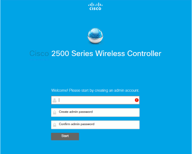
In Version 7.half dozen.130 and subsequently, the WLC offers an Express version of the GUI. Information technology is a way to configure it via the GUI, but is likewise a simplified monitoring dashboard that shows the kickoff fourth dimension you connect.
On the offset GUI connection you volition see this:

This page shows all monitoring data in an easy and attainable style. In social club to reach the "old" and complete GUI, you can clickAdvanced in the upper right corner. Once y'all are in Advanced way, you cannot get back to the express GUI unless you lot configured the WLC. As a benefit of the Express Setup GUI, you volition have a home push button on the upper right corner of the WLC page to render to the Express monitoring page.
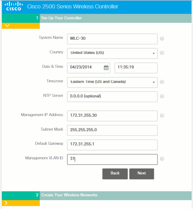
In order to configure the 2504 via the Express Setup GUI, you demand to connect a PC to port two, expect for the SYS led to turn green, and then browse to 192.168.1.i in your browser. This only works on port 2, which allows you to connect port ane of the WLC for network connectivity.
Configuration of the controller via the Express Setup GUI also changes various default settings to better match pocket-size businesses deployments.

A special wizard volition then appear for configuration:
Note: The express GUI setup wizard (Twenty-four hour period 0 interface) can be accessed through either a wired continued client or a wireless client. The like shooting fish in a barrel GUI setup wizard on a wired connection only appears when y'all plug in a wired client and at that place are no access points to the controller. If you plug in an access point that starts to broadcast the CiscoAirprovision SSID, the wired GUI sorcerer is no longer accessible and the easy GUI setup configuration tin can be completed just through a wireless client that is connected on the SSID. Therefore, it is either wired or wireless, merely this GUI wizard does not piece of work on both simultaneously.
In Release seven.five software code and afterward, the 2500 tin be purchased as HA-SKU. This means that the 2504 can then act as North+1 WLC. It still does not support AP SSO.
The HA SKU WLC does not require a license and stands there in example whatsoever other WLC of its mobility group fails. It can then support a maximum AP count license for 90 days, which starts when the original WLC failed and when APS started to bring together the HA-SKU. At that place is no configuration replication in N+1 redudancy. Bank check the High Availability deployment guide for more information on HA.
It is likewise possible to turn a not-HA SKU WLC into an HA SKU when you enable the HA SKU secondary unit of measurement :


How To Add Access Point To Cisco Wireless Controller 2504,
Source: https://www.cisco.com/c/en/us/support/docs/wireless/2500-series-wireless-controllers/113034-2500-deploy-guide-00.html
Posted by: orrisdocials.blogspot.com
0 Response to "How To Add Access Point To Cisco Wireless Controller 2504"
Post a Comment