

How To Use Arduino To Control Actual Lamp
In this tutorial, I'll show you how to use an Arduino to control LEDs. This is a pretty unproblematic project, but you should acquire how to do it early on considering lots of other sensors and modules are programmed the exact same way.

First I'll show you how to turn on and off the Arduino's on-board LED. So I'll show yous how to turn on and off an LED connected to one of the Arduino's digital pins. I'll explain how to change the LEDs flashing charge per unit, and how to change the pin that powers the LED. At the end I'll evidence you lot how to command multiple LEDs. Before starting, y'all should accept the Arduino IDE software installed on your calculator.
Electric Signals
The Arduino communicates with modules and sensors by switching on and off electrical current. Information technology's very like to the ane's and nothing's in binary code. When current is switched on, it'southward known equally a "High signal". That'southward comparable to the "one" in binary code. When the current is switched off, that's a "Low signal", which is similar to the zero in binary lawmaking. The length of time the current stays on or off can exist changed from a microsecond upwards to many minutes.
BONUS: I made a quick start guide for this tutorial that you lot tin can download and go back to later on if you can't set up this up right now. It covers all of the steps, diagrams, and code you need to get started.
Controlling the Arduino's LED
To turn on an LED, the Arduino needs to send a HIGH signal to 1 of it's pins. To plough off the LED, it needs to send a LOW indicate to the pin. You tin make the LED flash by irresolute the length of the HIGH and LOW states.
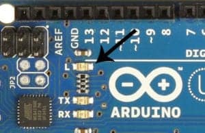
The Arduino has an on-board surface mount LED that'due south hard wired to digital pin 13. It'due south the ane with an "L" next to it:
To get this LED flashing, upload the "Blink" program to your Arduino:
void setup() { pinMode(13, OUTPUT); } void loop() { digitalWrite(13, HIGH); delay(1000); digitalWrite(xiii, LOW); filibuster(m); } The LED should at present exist blinking on and off at a rate of chiliad milliseconds (1000 milliseconds = 1 2d).
The delay() function on line 6 tells the Arduino to hold the HIGH signal at pivot 13 for yard ms. The delay() role on line 8 tells it to hold the LOW betoken at pin 13 for 1000 ms. You can alter the blinking speed by changing the number inside the parentheses of the delay() functions.
Controlling an External LED
An external LED or any other powered module tin be controlled in a like fashion.
LEDs need to have a resistor placedin serial (in-line) with it. Otherwise, the unrestricted electric current will quickly burn out the LED. The resistor can be whatever value between 100 Ohms and about 10K Ohms. Lower value resistors volition allow more than current to menstruation, which makes the LED brighter. Higher value resistors will restrict the electric current menses, which makes the LED dimmer.

Also, most LED's have polarity, which means that they demand to exist connected the right way around. Ordinarily, the LED's shortest lead connects to the ground side.
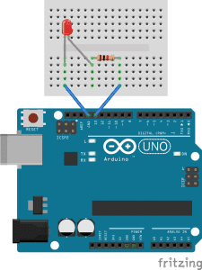
If you connect the LED to pin 13 equally shown in the epitome below, you can employ the aforementioned code we used above to make the LED flash on and off.
Changing the Pin
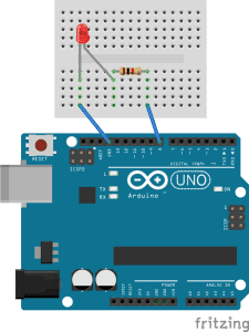
If y'all want to employ a different pin to power the LED, it's easy to change it. For instance, say you want to use pin 8 instead of pin 13. Kickoff motion the indicate wire from pin 13 over to pivot 8:
At present y'all'll need to edit a line of lawmaking in the program so the Arduino knows which pins to use as output pins. That'south washed on line ii of the lawmaking above, where information technology says:
pinMode(13, OUTPUT);
To use pivot 8, you lot merely have to change the 13 to an 8:
pinMode(viii, OUTPUT);
Next you'll need to change the code that tells the Arduino which pins volition get the HIGH and LOW output signals. That's done everywhere there's a digitalWrite() part. In the program above, there's 1 on line v and one on line 7:
digitalWrite(13, Loftier);
digitalWrite(xiii, Low);
To specify that pin eight should get the Loftier and LOW signals, you but need to change the 13's to viii's:
digitalWrite(eight, HIGH);
digitalWrite(8, Depression);
The finished program should look similar this:
void setup() { pinMode(8, OUTPUT); } void loop() { digitalWrite(eight, HIGH); delay(1000); digitalWrite(8, Low); delay(yard); } After uploading, the LED should flash just similar it did when it was continued to pivot 13.

Decision-making Multiple LEDs Together
Y'all can control as many LEDs as yous want as long equally you have plenty pins available. Let'southward make the external LED wink forth side the on-board LED to demonstrate. All we need to do is duplicate the code for pin eight, and change the pin numbers to pin 13.
Here'southward an example of that:
void setup() { pinMode(8, OUTPUT); pinMode(13, OUTPUT); } void loop() { digitalWrite(viii, Loftier); filibuster(1000); digitalWrite(13, HIGH); delay(1000); digitalWrite(8, Depression); filibuster(1000); digitalWrite(13, LOW); delay(yard); } You should be able to see both LEDs blinking. But they won't be blinking in sync, they'll be alternate.
The Arduino executes the instructions in the code from top to bottom. Information technology reads each line and performs the job earlier moving onto the side by side line. Once it has read through to the end, it loops back to line six and starts over once again.
In the programme in a higher place, the code is executed in this order:
- Loftier signal sent to pin 8
- Wait for 1000 ms
- Loftier indicate sent to pivot 13
- Wait for grand ms
- LOW signal sent to pin 8
- Wait for thou ms
- LOW indicate sent to pin 13
- Expect for chiliad ms
- Return to step one
To get both LEDs blinking at the same time, nosotros need to remove the delay between the HIGH and LOW signals of each pin, every bit shown in this programme:
void setup() { pinMode(8, OUTPUT); pinMode(thirteen, OUTPUT); } void loop() { digitalWrite(8, HIGH); digitalWrite(13, HIGH); delay(chiliad); digitalWrite(8, Low); digitalWrite(xiii, LOW); delay(1000); } Now both LEDs should turn on and off at the same time. The tasks are executed in this order:
- HIGH signal sent to pin eight
- HIGH indicate sent to pin 13
- Wait for 1000 ms
- Depression signal sent to pin 8
- Depression signal sent to pin 13
- Wait for 1000 ms
- Return to stride i
Now that you've seen how to command LEDs with the Arduino, cheque out part 2 of this series, where I'll testify you how to use a light dependent resistor to command how fast the LED flashes and how to command the pitch of sound output past a speaker.
If you have any questions or accept trouble getting this project to piece of work, just leave a comment below and I'll try aid yous get information technology going. And be certain to subscribe! We transport out an email each time we publish a new tutorial…

How To Use Arduino To Control Actual Lamp,
Source: https://www.circuitbasics.com/arduino-basics-controlling-led/
Posted by: orrisdocials.blogspot.com
0 Response to "How To Use Arduino To Control Actual Lamp"
Post a Comment